
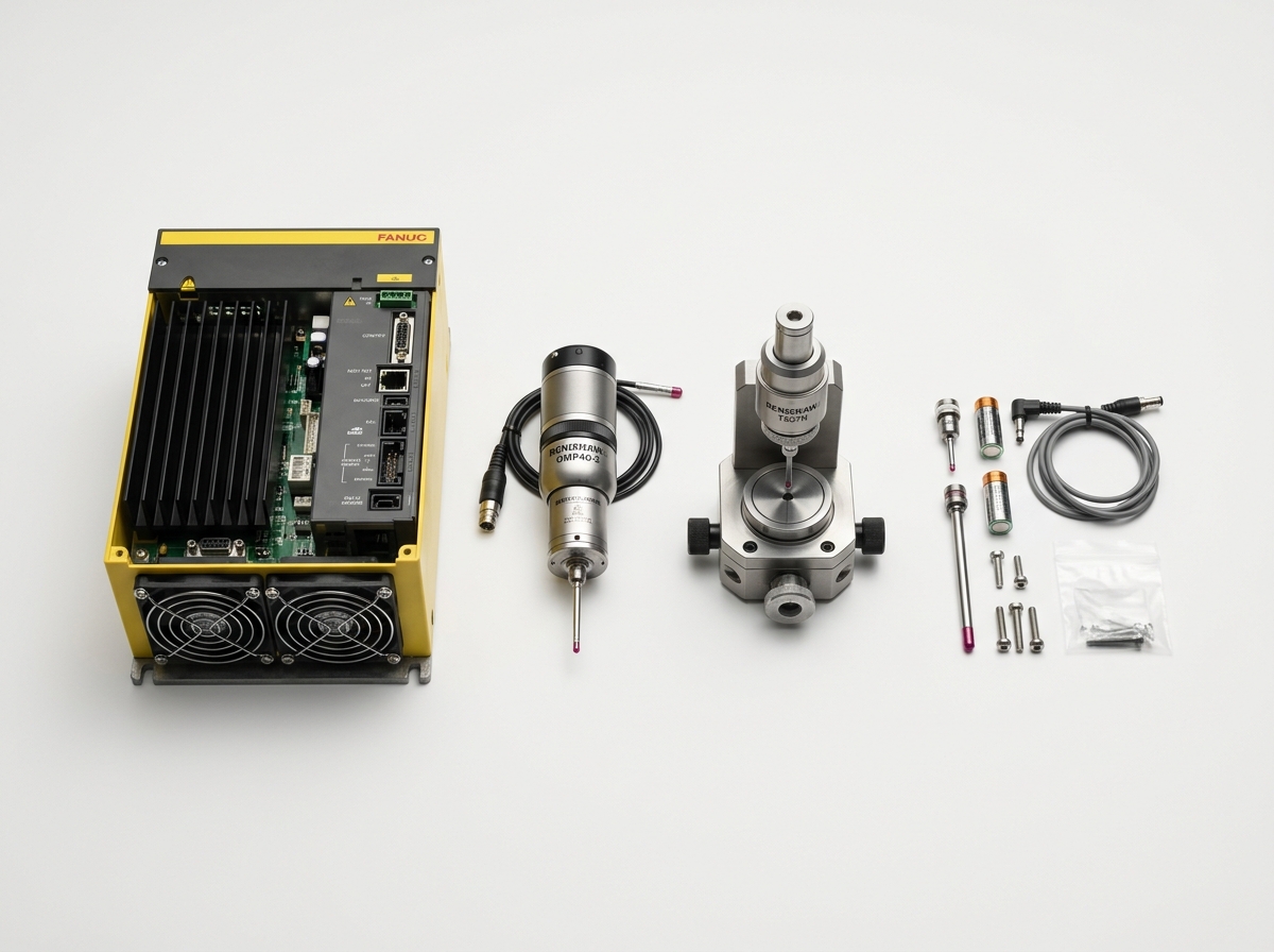
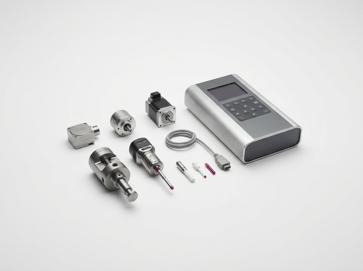
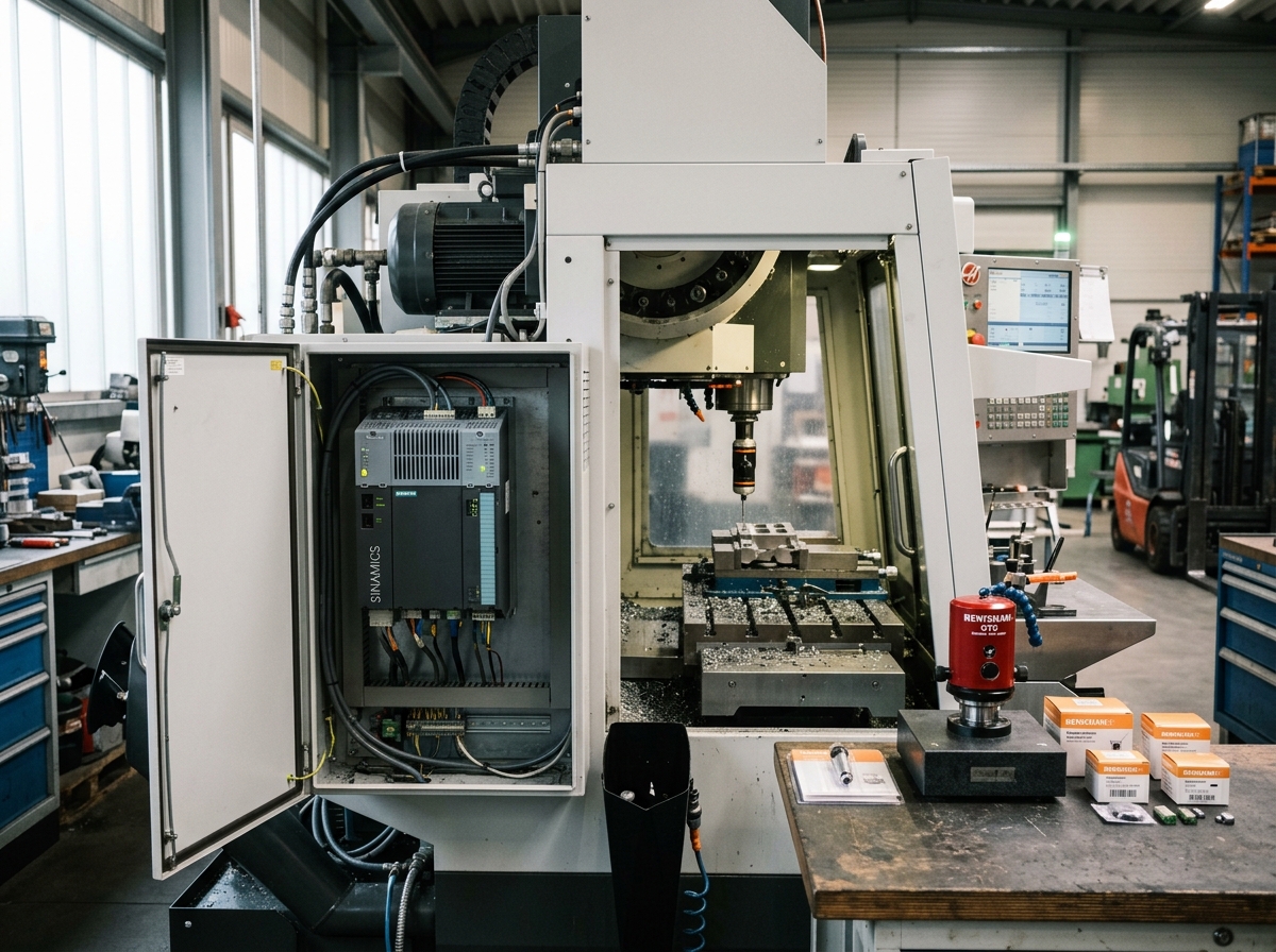
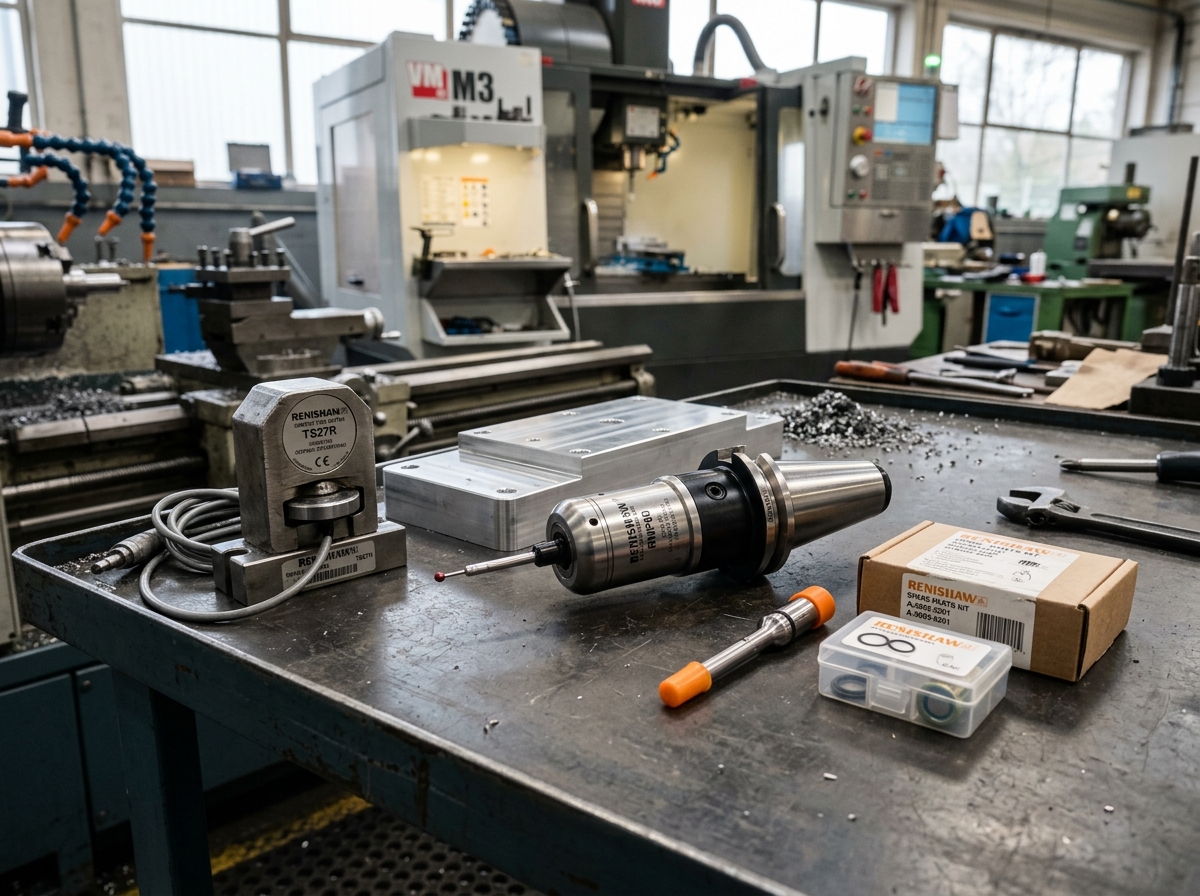
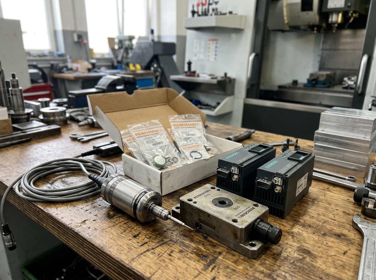
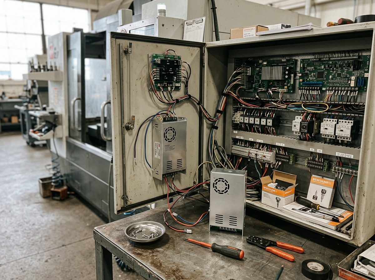
- Match the module to the controller’s electrical standard first, not the catalog price.
- Separate control I/O, safety I/O, and high-speed signals to reduce false alarms.
- Look for isolation, diagnostic LEDs, and fast replacement support to minimize downtime.
- Use the signal list from the cell design before ordering any replacement part.
A CNC I/O module is the interface that lets a CNC controller communicate with peripheral devices in an automation line, and that interface quality can determine whether a cell runs smoothly or stops on a simple handshake fault. In high-volume machining, even a small mismatch in voltage, common return, or output load type can create intermittent failures that are hard to diagnose. For machine-tool positioning and verification, industry users often rely on tight repeatability standards such as ISO 230-1:2022, while closed-loop feedback systems may be evaluated against encoder and measurement practices documented by NIST. If you are comparing spare parts, start with the full signal map, then match the module to the controller family, the fixture logic, and the downtime risk profile. For related components, review the servo drive options, encoder products, and power supply units before finalizing the I/O architecture.
How a CNC I/O module fits into an automation line
The CNC I/O module is the traffic controller for external signals, and its job is to keep the machine, fixtures, sensors, and auxiliary devices synchronized. In a typical automation line, the CNC sends outputs for clamp open, clamp close, pallet ready, door lock, mist collector start, and robot request, while the line sends inputs for part present, pressure OK, home complete, alarm reset, and cycle complete. That means one faulty bit can block the entire cycle.
Signal integrity matters because industrial control wiring is exposed to electrical noise, long cable runs, and grounding problems. A robust module design usually includes optical isolation, clear LED indication, and channel-level diagnostics. In many retrofit jobs, the fastest way to reduce troubleshooting time is to map every external device to a unique channel number and label the terminal plan before installation.
| Common automation signal | Typical direction | Why it matters | Failure symptom |
|---|---|---|---|
| Part present sensor | Input | Confirms the workpiece is loaded | Cycle will not start |
| Fixture clamp status | Input | Verifies workholding safety | False safe state or alarm |
| Robot ready | Input | Coordinates cell handoff | Wait state or deadlock |
| Clamp open/close | Output | Controls pneumatic or hydraulic action | Part misload or collision risk |
| Cycle complete | Output | Signals the next station | Line stops at transfer point |
CNC I/O module selection criteria for automation line reliability
The best CNC I/O module is the one that matches the controller’s electrical behavior and the cell’s operating conditions. Buyers should evaluate six technical points before ordering: voltage rating, input style, output style, isolation, response time, and expandability. These are not abstract catalog items; they determine whether the module survives daily production or becomes a recurring service call.
For voltage, many industrial control systems use 24 VDC, but the signal type matters as much as the voltage. Sinking and sourcing logic must match the controller and peripheral equipment. A mismatch can make an input appear permanently on or permanently off. Likewise, relay outputs may suit low-frequency switching, while transistor outputs are preferred when the line needs higher switching speed and longer life. When the automation line includes proximity sensors, photoelectric sensors, and pneumatic valves, the output load current should be checked carefully so the module is not overstressed.
| Selection factor | What to verify | Typical value or range | Why it matters |
|---|---|---|---|
| Control voltage | Controller and field device standard | 24 VDC is common | Prevents miswiring and logic faults |
| Isolation | Channel or group isolation | 1 kV class is common in industrial modules | Helps protect the controller from noise and transients |
| Output type | Relay or transistor | Relay for low-frequency, transistor for faster switching | Affects speed, lifespan, and load compatibility |
| Input response | Pulse detection or scan speed | Faster modules are needed for short pulses | Prevents missed events |
| Environmental rating | Temperature, vibration, and enclosure fit | Industrial control cabinets vary by machine | Supports stable long-term operation |
| Expansion | Extra channels for future devices | Plan 10% to 20% spare capacity | Reduces redesign during line changes |
In retrofit work, spare capacity is not waste; it is insurance against late-stage engineering changes. A line that starts with a robot, a clamp, and a sensor often ends up adding a rejection gate, a stack light, or a quality probe. If the module has no spare channels, the plant may need a second cabinet revision, extra wiring, and a production stop.
What signal input output architecture should you choose
The signal input output architecture should be designed around function, not just channel count. For example, a CNC automation line usually benefits from separating standard process I/O from safety-related signals and from high-speed measurement signals. That separation improves troubleshooting and reduces the chance that a noisy peripheral will disturb a critical control path.
Standard process I/O handles clamp status, part detection, alarms, and cycle handshakes. Safety circuits should remain in dedicated safety relays or safety controllers rather than being treated as ordinary process outputs. High-speed inputs may be needed for short encoder pulses, fine timing events, or fast part counting. If every signal is forced into a generic module, the system becomes harder to diagnose and more vulnerable to nuisance trips.
- Use dedicated channels for machine start, stop, and reset functions.
- Keep sensor returns organized by group to simplify troubleshooting.
- Use shielded cable and proper grounding for long sensor runs.
- Reserve extra channels for future devices and maintenance bypasses.
For shops that also rely on feedback devices, the surrounding ecosystem matters. A stable servo motor can reduce motion errors, while a correctly configured linear scale can support tighter closed-loop positioning. In many cases, the I/O module is the least visible part of the system, but it is the one that decides whether all those components can communicate reliably.
How to compare relay output and transistor output modules
Relay output modules and transistor output modules solve different problems, and choosing the wrong one creates avoidable downtime. Relay outputs are mechanically switched and work well for moderate-speed on/off control, especially when the load type varies. Transistor outputs switch electronically, so they are better suited to rapid cycling and a higher duty rate. The tradeoff is that transistor modules are more sensitive to load polarity and current limits.
In a CNC automation line, relay outputs are often acceptable for door interlocks, coolant commands, or stack light control, while transistor outputs are a better match for fast solenoid cycling, pallet transfer, and repetitive part-handling commands. If the line sends thousands of cycles per shift, the mechanical wear of relays can become a maintenance issue. If the line only switches occasionally, relay flexibility may be more useful.
| Output type | Strength | Limitation | Best use case |
|---|---|---|---|
| Relay | Flexible load compatibility | Mechanical wear over time | Interlocks, lights, low-frequency control |
| Transistor | Fast switching and long electrical life | Requires correct polarity and current control | Solenoids, rapid handshakes, high-cycle automation |
| Hybrid or mixed output design | Task-specific signal allocation | More planning required | Cells with both slow and fast devices |
A practical rule is simple: if the output must switch often, choose electronic switching; if the output must tolerate varied loads, test the relay option carefully. In both cases, confirm the load current against the module specification and leave thermal margin for cabinet conditions.
Which standards and test references should guide your decision
Standards help buyers separate marketing claims from engineering reality, and they are especially useful when comparing replacement parts across brands. For machine-tool acceptance and positioning concepts, ISO 230-1:2022 is a useful reference point because it defines test principles for machine tool performance. For dimensional tolerances and geometric verification in manufactured parts, ISO 2768-1 is often used as a general reference for unspecified tolerances. For electrical and automation documentation practices, many factories also consult official guidance from NIST to support measurement integrity and traceability.
These references do not tell you which module to buy, but they shape how you verify the whole system. A module should be tested under the same cabinet conditions, wiring practices, and noise environment that it will see in production. If your line is sensitive to timing, record input response behavior during commissioning rather than assuming catalog values will hold under load.
Quantitatively, many industrial automation systems are built around 24 VDC control circuits, and well-managed machine tools often aim to keep signal-related failures near zero during a shift. In practice, the biggest savings come from avoiding false alarms and reducing troubleshooting time, not from shaving a few dollars off the purchase price. According to industry maintenance practices, a well-labeled and modular signal layout can cut fault isolation time substantially, especially in multi-axis cells with robot handshakes and pneumatic fixtures.

How to avoid the most common CNC I/O module buying mistakes
The most expensive CNC I/O module mistake is usually a compatibility mistake, not a product defect. Buyers often focus on the number of channels and overlook the electrical logic, cable terminations, or controller compatibility. That is why spare-part procurement in CNC environments should always begin with model matching, interface matching, and control logic matching.
- Do not buy by channel count alone; verify input and output types first.
- Do not assume two 24 VDC modules are interchangeable; check sinking, sourcing, and common wiring.
- Do not mix safety signals with standard process signals in one generic channel group.
- Do not ignore cabinet heat, vibration, and dust when comparing modules.
- Do not skip the wiring diagram review before installation.
When a line is down, maintenance teams often care more about replacement speed than about feature richness. That is why suppliers with strong part identification and inventory depth usually have an advantage in real production environments. If the part must be replaced quickly, the right question is not “Which module is cheapest?” but “Which module can be confirmed, shipped, and installed with the least risk?”
Practical checklist for buying a CNC I/O module
A short checklist is often the fastest way to prevent ordering errors. Before purchase, gather the controller model, the existing terminal photo, the wiring diagram, the load list, and the fault history. Then compare the candidate module against those documents line by line.
- Controller model and firmware family
- Input voltage and logic type
- Output type, load current, and duty cycle
- Number of channels used today and channels reserved for growth
- Mounting style, connector type, and cabinet space
- Required diagnostics such as LEDs or fault indication
- Expected replacement lead time and local spare strategy
For plants that maintain multiple machine brands, standardizing on a documented signal naming convention pays off quickly. A clear tag name for every sensor, valve, and handshake line reduces training time and lowers the chance of miswiring after maintenance. It also makes it easier to swap parts across shifts and sites without creating hidden logic errors.
How I/O module choice affects uptime, not just wiring
The I/O module affects uptime because it sits between the controller’s decisions and the physical machine actions. If its diagnostics are poor, a one-minute fault can become a one-hour search. If its isolation is weak, a noisy valve or damaged cable can trigger repeated stops. If its output rating is too low, contacts may wear prematurely and create intermittent behavior that looks like a software issue.
In high-mix production, these issues are amplified because the line changes part types, fixture programs, and operator routines throughout the day. A good module helps absorb that variability. A poor one exposes it. That is why buyers should think in terms of total cost of ownership: installation time, alarm rate, troubleshooting effort, and spare-parts continuity.
When the automation line is part of a broader CNC system, it also helps to review adjacent components such as the CNC control systems and HMI panels. Clear operator feedback and controller-side diagnostics often reduce the load on the I/O module because issues can be caught earlier in the sequence.
FAQ
What is the most important factor when choosing a CNC I/O module?
The most important factor is compatibility with the controller’s electrical logic and the automation line’s signal map. Voltage alone is not enough; you must confirm input type, output type, isolation, and wiring method.
Should I choose relay output or transistor output?
Choose relay output for lower-frequency, flexible-load switching and transistor output for faster, high-cycle automation tasks. If the line cycles frequently, transistor output is usually the better long-term choice.
How many spare channels should I plan for?
A practical planning range is 10% to 20% spare channel capacity, especially in lines that may add sensors, stack lights, or transfer devices later.
Why do I need isolation in an I/O module?
Isolation helps protect the controller from electrical noise, transients, and wiring faults. It is especially useful in cabinets with solenoids, long cable runs, or mixed-noise environments.
Can I reuse an old I/O module from a different machine brand?
Only if the voltage, logic type, connector standard, and controller communication requirements all match. Brand similarity alone is not enough to guarantee safe operation.
What causes false input signals in automation lines?
Common causes include poor grounding, damaged cables, electromagnetic noise, loose terminals, and mismatched sinking or sourcing logic.
How do I reduce downtime when replacing an I/O module?
Keep the wiring diagram, terminal photos, controller model, and fault history ready before ordering. Fast part identification and clear labeling usually reduce replacement time more than any minor hardware difference.